


Online consultation
Go at once >>


 UL Automatic Control Cabinet
 UL Medium And High Voltage Switchgear
 UL Low voltage switchgear
 UL distribution cabinet


UL Low voltage power distribution and control system
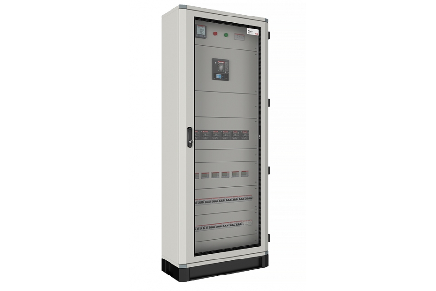
The UL low-voltage distribution power and power control package, which incorporates UL's next-generation design platform, provides a highly safe, functional and flexible solution that enables the digital, industrial and general functions of the entire system to ensure reliable and fast application packages.
Digital smart power distribution and three boxes: Intelligent interconnection with ABB Ability cloud platform, eEMS studio local energy efficiency platform and third-party platform to achieve digital operation and maintenance management, providing support for carbon emission analysis and energy saving and efficiency
Focus on more industry-specific solutions: medical IT power supply, data center precision distribution head cabinet...
Typical solutions, rich and practical: Provides a range of high-performance solutions for typical power distribution, lighting, power and control applications
Consistent, easy to use: maintain a consistent main structure safe and reliable, upgraded unique appearance Angle design, beautiful and recognizable, more suitable for complete assembly, convenient on-site installation, more simple and efficient customer post-operation and maintenance experience
Through the UL certification (UL:Underwriter Laboratories Inc.) Underwriters Laboratory of America
UL Low voltage systems provide advanced solutions for power distribution and motor control
MNS switchgear with integrated power and automation for customers in the process industry, power and infrastructure industries
Produced by Witu factory in Germany, it is a control box made of thermoplastic materials combined with injection molding technology. The outer surface is hard and the inner layer is fluffy. It has the same physical characteristics as polyester material, which can effectively ensure that the entire box is exceptionally strong. Also, mixed with fiberglass
Unlike the polyester material control box, it does not contain fiberglass, so there is no need to worry about the exposure of fiberglass over time to the operation and safety of the control box. The multifunctional control box has a protection rating of up to IP66 (IP30 after the installation of components).
It is also highly resistant to chemicals and climatic conditions, ensuring good product performance even under harsh working conditions. In distribution and hybrid applications, the multi-function control box can be equipped with Systempro M series modularization devices and Tmax
Plastic-case circuit breakers and control and signal devices to form a truly integrated automation system.
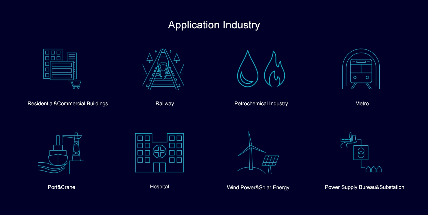
Suitable for shipbuilding, solar energy, water treatment, rail transit, metallurgy, petrochemical, communication and traditional machinery and other industries. Can be customized for different needs of customers.
Different motor starting control modes are supported by parameter setting, and the running state of contactor is detected by state feedback of contactor auxiliary contact. The control authority of the motor includes local control and remote control.
Maximum frame size rating* by module size (fuseless)
|
400/415V, 65kA, IE3 |
XS size |
S size |
M size |
L size |
XL size |
|
Feeder 3 pole |
63 A |
250 A |
400 A |
630 A |
- |
|
Feeder 4 pole |
63 A |
160 A |
380 A |
400 A |
630 A |
|
|
|
|
|
|
|
|
DOL (EOL) |
22 kW |
55 kW |
160 kW |
- |
250 kW |
|
HDOL (EOL) |
22 kW |
55 kW |
160 kW |
- |
- |
|
REV (EOL) |
7.5 kW |
30 kW |
75 kW |
160 kW |
- |
|
|
|
|
|
|
|
|
DOL (M10x) |
22 kW |
55 kW |
160 kW |
- |
250 kW |
|
HDOL (M10x) |
22 kW |
55 kW |
160 kW |
- |
- |
|
REV (M10x) |
7.5 kW |
30 kW |
75 kW |
160 kW |
- |
|
|
|
|
|
|
|
|
DOL (UMC) |
22 kW |
55 kW |
160 kW |
- |
250 kW |
|
HDOL (UMC) |
22 kW |
55 kW |
160 kW |
- |
- |
|
REV (UMC) |
7.5 kW |
30 kW |
75 kW |
160 kW |
- |
Various necessary motor starting control methods are integrated into the device. The user can directly select the desired starting control mode in the M10x motor control interface.
The box with control button means that the contactor can be controlled directly through the control button without the M10x.
Reverse - Direct start (with limit switch) The reverse - direct start mode with limit switch refers to the reverse - direct start mode that needs to be stopped by the position switch, such as valve, damper, actuator control, etc.
The feed unit control mode is a special starting mode supported by M10x, which is used for the control and detection of the MCCB feed circuit of the live operating mechanism.
The M10x offers complete motor protection. Perfect motor protection is to collect and track the detailed information of various operating conditions during the operation of the motor, through the setting of fault alarm, protection action (protection trip) and action delay time
Accurate protection to ensure the safety of production. At the same time, the detailed information of motor running condition can be detected in real time on the host computer through communication, which provides the basis for process analysis and management optimization. Before the equipment may have a major failure, the alarm can be exceeded
Timely remind management personnel to deal with it, avoid unnecessary downtime affecting normal production, and ensure the effectiveness of equipment operation as far as possible.
When the motor running parameters reach the preset alarm value, the protection device will alarm and report. When the preset trip value is exceeded, the timer will be activated and the motor will enter the trip countdown state. The countdown time is set according to the blurt delay parameter.
As long as the fault persists, the countdown will continue. After the setting delay time is exceeded, the motor will eventually stop. If the fault is rectified before the countdown ends, the timer will reset and shut down, and the motor will not stop. If the above occurs, an event record is generated
Message. In addition, operational data such as trip time and reset time can be collected and reported via the fieldbus.
|
Protection function |
Description |
M101 |
M102 |
|
Long start time protection |
Protect the motor from blocking during starting. |
§ |
§ |
|
Thermal overload protection |
Thermal overload protection is to protect the motor from overheating by tracking and calculating the heat capacity of the motor in operation 。 |
§ |
§ |
|
Thermal overload protection for explosion-proof motor EEx e |
EEx eThe protection takes into account the ratio of the motor locked-current to the nominal current and the maximum motor temperature allowed by the corresponding environmental class。 |
§ |
§ |
|
Start limit protection |
Limit the number of motor starts within a certain time interval。 |
§ |
§ |
|
Off-phase protection |
Determine whether to start the phase break protection function according to the ratio of minimum line current to maximum line current。 |
§ |
§ |
|
Phase unbalance protection |
Poor conductor contact, motor failure or loose wiring will lead to phase imbalance. The difference between the minimum line current and the maximum line current can be determined according to the set parameters. The IEEE standard does not support inverting protection. |
§ |
§ |
|
Locked-rotor protection |
Determine whether to start the lock rotor protection according to the ratio of the measured value of the maximum line current and the rated current of the motor. This function only takes effect after the motor starting time has passed。 |
§ |
§ |
|
Undervoltage protection |
This function protects the motor under low voltage conditions (voltage drop or power failure)。 |
|
§ |
|
Automatic restart |
It is divided into standard type and enhanced type。 |
|
§ |
|
Light load protection |
According to the ratio of the maximum line current to the rated current 。 |
§ |
§ |
|
No-load protection |
It is similar to the light-load protection, but the alarm value, trip value, and fault information are different。 |
§ |
§ |
|
Earth fault protection |
The ground fault protection of the motor is realized by adding zero sequence current transformer, adjustable fault current trip value and delay time。 |
§ |
§ |
|
Motor thermal protection(PTC) |
Protection is achieved by detecting the resistance value of the PTC thermistor embedded in the motor winding。 |
|
§ |
|
Motor thermal protection (with PTC relay) |
The resistance value of PTC thermistor embedded in the motor winding is detected by an external PTC relay。 |
§ |
§ |
|
Motor thermal protection (using RTD relays) |
The protection is realized by the detection of PT100 resistance embedded in the motor winding by an external RTD relay。 |
§ |
§ |
|
Phase sequence protection |
Before the motor starts, phase sequence protection is based on voltage detection, and after the motor starts, phase sequence protection is based on current detection。 |
§ |
§ |
、

Follow Xuanhong wechat public number

